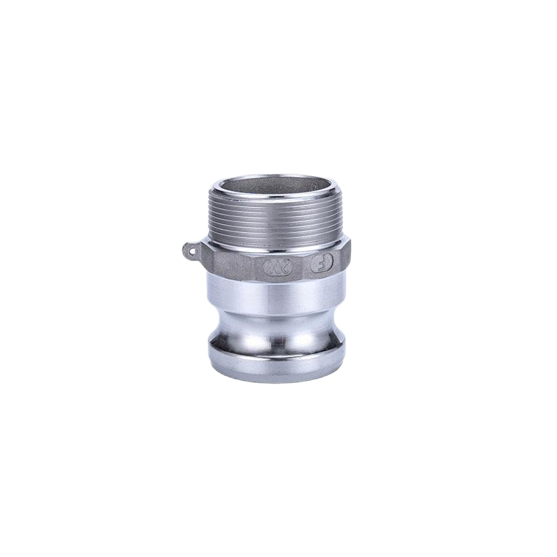
Aluminum camlock fitting Type F
Introduction:
Aluminum Camlock Couplings manufactured in accordance with standard A-A-59326(replacing original standard Mil-C-27487) or EN14420-7(replacing DIN 2828), size from 1/2″ to 8″. The coupling of cam grooves between manufacturers is interchangeable, except for 1/2″(12.7 mm), 5″(127 mm) and 8″(203.2 mm).and A-A-59326 can be coupled with the camlcok coupling of the EN14420-7(substituted DIN 2828), but the two standard tube tails are different.
Camlock couplings provide a simple and reliable method for connecting and disconnecting hoses, with good wear resistance, chemical resistance and economic cost. These camlock couplings can transport gasoline, heavy oil, kerosene, water, mud, salt water, acid and alkaline fluid media by connecting PVC pipes, rubber hoses, etc. It has the advantages of quick connection, flexible disassembly and labor saving
Description:
- Body Material: Aluminum
- Handle: Stainless steel or Brass
- Gaskets:NBR,PTFE,viton,EPDM etc
- The thread of camlock fittings are BSP,BSPT,NPT,G (ISO 228.1) and R (DIN2999).
- Size:1/2″to 8″
- Working pressure :50-250 Psi( depending on size and temperature)
- Manufacture method:gravity casting
The use and connection way of the cam and groove couplings: Type F camlock can usually be used with D type, C type, DC type. To make a connection,simply slide the camlock adapter into the camlock coupling and with normal hand pressure,press the cam levers down.
Feature:
- Light weight, convenient and interchangeable
- Easily disconnect/connect without tools
- Economic utility
Industry applications:
- Industry: Petroleum, mining, municipal, construction, chemicals, agriculture
- Applications: Hydraulic fluids, coolant, gasoline and petroleum products, fuel transportation, irrigation, water treatment, brine, wastewater, chemicals transport and storage,etc.
Aluminum camlock couplings operating pressure:
| Size | Working Pressure |
| 1/2” – 4” | 150 Psi |
| 5” – 6” | 75 Psi |
| 8” | 50 Psi |
Aluminum camlock couplings male adapter Type F:
Unit:mm
| Part No | A | B | C | D | E |  |
| 050 | 26.6 | 17 | 10 | 26 | 53 | |
| 075 | 32.4 | 19 | 10 | 26 | 55 | |
| 100 | 38.5 | 19 | 14 | 34.8 | 67.8 | |
| 125 | 47 | 24 | 14 | 40 | 78 | |
| 150 | 56 | 22 | 13 | 41 | 76 | |
| 200 | 65 | 24.5 | 13 | 46 | 83.5 | |
| 250 | 80 | 29 | 16 | 50 | 97 | |
| 300 | 95 | 31.5 | 17 | 48 | 99 | |
| 400 | 122.5 | 33 | 19 | 53.8 | 105.8 | |
| 500 | 150 | 37 | 22.5 | 57 | 112.5 | |
| 600 | 181 | 40.5 | 22.5 | 57.3 | 120.3 |


