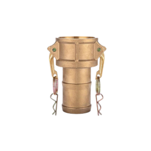
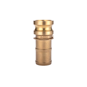
Brass camlock fitting Tyep A
Introduction:
Brass cam and groove coupler &adapter are made according to standard A-A-59326(original standard Mil-C-27487), size from 1/2″ to 6″.Camlock coupling provides a simple and reliable way to connect and disconnect the hose. During installation, no tools are needed, and the handle can be pressed by hand, which can save time, tools and manpower. Brass camlock suitable for conveying water, coolant, hydraulic oil, gasoline and petroleum products.
Description:
- body materials: Brass
- handle: Brass
- Gaskets:Buna-N (NBR), EPDM
- The thread of camlock fittings are BSP,BSPT,NPT,G (ISO 228.1) and R (DIN2999).
- SIZE:1/2″to 6″
- pressure :75-250 Psi( depending on size and temperature)
- Operating temperature :-40 to 145℃
- Manufacture method:Forging and casting
Cam and groove couplings use and connection mode: Type A camlock can usually be used with type D, type C, type B, type DC (Dust Cap) of the same size. To make a connection, simply slide the camlock adapter into the camlock coupling and with normal hand pressure, press the cam levers down.
Feature:
- Convenience, interchangeability
- Good corrosion resistance
- Its special non-sparking feature
- longer service life
- Easily disconnect/connect without tools
Industry applications:
- industries: petroleum, mining, municipal, construction, marine refueling systems
- applications: hydraulic oil, coolant, gasoline and petroleum products, fuel delivery, water treatment, brine, wastewater
Operating pressure:
| Size | Working Pressure |
| 1/2” – 2” | 250 Psi |
| 2-1/2” | 150 Psi |
| 3” | 125 psi |
| 4” | 100 psi |
| 5” – 6” | 75 psi |
Size diagram:
Unit:mm
| Part No | A | B | C | 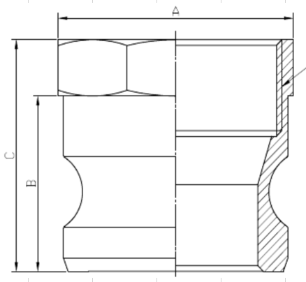 |
| 050 | 24.4 | 26 | 41 | |
| 075 | 32.4 | 26 | 41 | |
| 100 | 38.5 | 34.8 | 51.6 | |
| 125 | 48.5 | 40 | 55 | |
| 150 | 56 | 41 | 56 | |
| 200 | 66 | 46 | 59 | |
| 250 | 80 | 50 | 68 | |
| 300 | 96 | 51 | 71.7 | |
| 400 | 122.5 | 53.8 | 73.8 | |
| 500 | 152 | 53 | 75.5 | |
| 600 | 181 | 57.3 | 79.8 |